实物介绍和接线说明
JGB37-520电机是一种直流减速电机,常使用TB6612电机驱动芯片来驱动

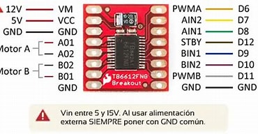
| TB6612芯片引脚 |
作用说明 |
接到哪里 |
| VM |
输出电压源 |
直接连到12V直流电源的正极 |
| VCC |
逻辑电路电源 |
可从单片机的5V输出引脚引入VCC |
| GND |
地 |
直接连到12V直流电源的负极
需要注意的是12V电路的GND要和5V电路的GND连接,也就是”共地”原则 |
| AO1,AO2 |
提供给电机A的输出电压 |
520电机的红线和白线 |
| BO1,BO2 |
提供给电机B的输出电压 |
第二个520电机的红线和白线 |
| AIN1,AIN2 |
决定电机A的转向 |
单片机分配的两个GPIO引脚 |
| BIN1,BIN2 |
决定电机B的转向 |
单片机分配的两个GPIO引脚 |
| PWMA |
控制电机A转速的PWM信号 |
单片机分配的一个定时器引脚 |
| PWMB |
控制电机B转速的PWM信号 |
单片机分配的一个定时器引脚 |
| STBY |
使能引脚,高电平使能芯片使之工作 |
单片机分配的一个GPIO引脚 |
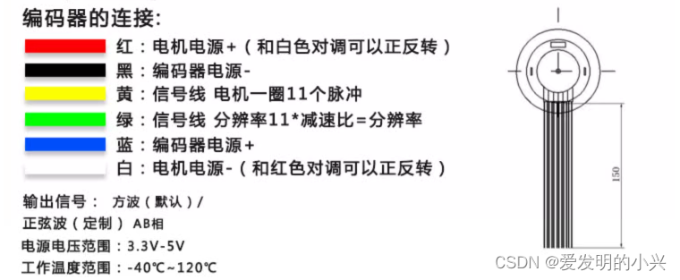
| JGB37-520电机线 |
接到哪里 |
| 红线,白线 |
上个表格已经提到,接到O1,O2上(可以调换顺序) |
| 蓝线,黑线 |
接到5V电源上,正负不可调换 |
| 黄线,绿线 |
接到单片机分配的两个定时器引脚上,(可以调换顺序) |
补充关于定时器的知识
我们此前使用的TIM14是STM32上搭载的最简单的一类定时器Basic Timer
这种定时器的功能基本就是单纯的计时
除此之外,STM32上还搭载了General Purpose Timer和Advanced-control Timer两种更高级的定时器
在这个项目中,我们需要用到(至少是)General Purpose Timer来解算电机编码器返回的信号和发送PWM信号
对于本项目使用的芯片STM32H750VBT6(没错又是它)来说,定时器TIM1和TIM8都是Advanced-control Timer。它们包含General Purpose Timer的所有功能。定时器TIM2~5,TIM12(被阉割了一部分功能), TIM15都是General Purpose Timer。
CubeMX工程配置
由于本文是520电机的使用介绍,所以重点介绍和电机有关的部分
定时器配置
编码器模式
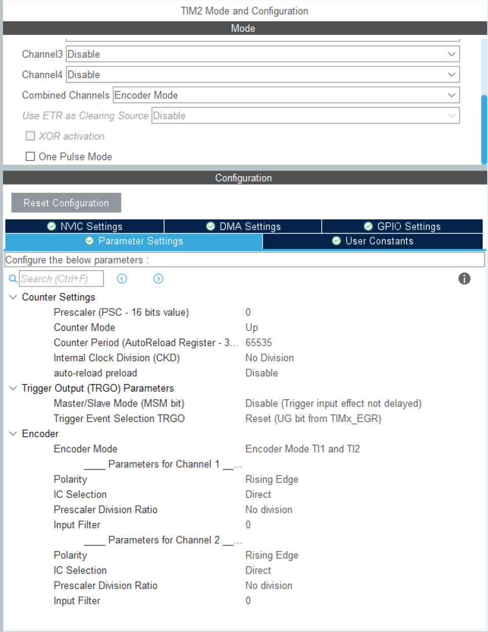
以TIM2为例,在Mode中找到Combined Channels这一项,选择Encoder Mode。这时上方有几个选项会变成灰色不可自行调整。这是因为我们选择了编码器模式,工程把TIM2的Channel 1和Channel 2自动分配为接收信号的引脚了。这就是连接520电机黄线和绿线的引脚。
编码器模式下,定时器会接收A相和B相的信号并自动计数——这样就得到了电机的编码器值。
接下来配置Parameter Settings。最重要的设置是Encoder Mode中选择Encoder Mode TI1 and TI2。此项将把编码器的精度提升4倍。
其他选择默认设置就好了
生成PWM信号
如果你不知道PWM
生成PWM信号的定时器通道可以是任何一个空闲的定时器通道。我这里选择让TIM1生成PWM信号。
需要几个PWM信号就设置几个通道(Channel)为PWM Generation CHx
提供给TB6612的PWM的信号周期为1ms就好了(不是也没关系),TB6612就看PWM的占空比
| Counter Settings |
Value |
| Prescaler |
240-1 |
| Counter Period |
1000-1 |

设置空余GPIO引脚
建议在设置完所有定时器,串口以及其他功能后再设置空闲GPIO
在右边的芯片视图挑方便你布线的引脚设置为所需的功能引脚,比如STBY、AIN1、AIN2, etc.
如果你有硬件帮你做板子那就让硬件挑他喜欢的引脚(当然,你的硬件同学要靠谱)
代码实现
首先定义一个结构体来打包电机的所有数据
1
2
3
4
5
6
7
8
9
10
11
12
13
14
15
16
17
18
19
20
21
22
23
24
25
26
27
28
29
30
|
typedef struct {
TIM_HandleTypeDef* pwm_tim;
HAL_TIM_ActiveChannel pwm_channel;
TIM_HandleTypeDef* enc_tim;
GPIO_TypeDef* en_port;
GPIO_TypeDef *In1_port,*In2_port;
uint16_t en_pin;
uint16_t In1_pin,In2_pin;
float rpm;
int32_t encoder_count;
int16_t current_count;
int16_t last_count;
uint32_t last_time;
uint32_t current_time;
uint32_t delta_time;
uint8_t encoding;
}jgb37_520_motor_t;
|
初始化函数当然少不了
1
2
3
4
5
6
7
8
9
10
11
12
13
14
15
16
17
18
19
20
21
22
23
24
25
26
27
28
29
30
31
32
33
34
35
36
37
| void JGB37_520_motor_init(jgb37_520_motor_t* motor,
TIM_HandleTypeDef* pwm_tim, uint32_t pwm_channel,
TIM_HandleTypeDef* enc_tim,
GPIO_TypeDef* en_port, uint16_t en_pin,
GPIO_TypeDef* In1_port, uint16_t In1_pin,
GPIO_TypeDef* In2_port, uint16_t In2_pin)
{
motor->pwm_tim = pwm_tim;
motor->pwm_channel = (HAL_TIM_ActiveChannel)pwm_channel;
motor->enc_tim = enc_tim;
motor->en_port = en_port;
motor->en_pin = en_pin;
motor->In1_port = In1_port;
motor->In1_pin = In1_pin;
motor->In2_port = In2_port;
motor->In2_pin = In2_pin;
motor->last_count = 0;
motor->last_time = 0;
motor->current_count = 0;
motor->current_time = 0;
motor->encoding = 0;
HAL_GPIO_WritePin(motor->en_port, motor->en_pin, GPIO_PIN_SET);
HAL_TIM_PWM_Start(motor->pwm_tim, motor->pwm_channel);
HAL_TIM_Encoder_Start(motor->enc_tim, TIM_CHANNEL_ALL);
__HAL_TIM_SET_COUNTER(&htim2, 0);
motor->encoder_count = __HAL_TIM_GET_COUNTER(motor->enc_tim);
return;
}
|
然后是反馈信号的处理
在前面的设置中,我们已经用定时器的Encoder Mode帮我们完成了解算的第一步——计数脉冲数
由单位时间内的新增脉冲数就可以计算出电机的实际转速
不应当选取过小的单位时间,比如1ms
电机的编码器精度没那么高,选取过小的单位时间会导致单位时间内新增的脉冲数只有个位数——这意味着被计算出来的电机速度只有个位数种情况
这反而会降低计算出的转速精度
1
2
3
4
5
6
7
8
9
10
11
12
13
14
15
16
17
18
19
20
21
22
23
24
25
26
27
28
29
30
31
32
33
34
35
36
37
38
|
void JGB37_520_motor_get(jgb37_520_motor_t* motor){
if ( motor->encoding == 1 ){
return;
}
if ( HAL_GetTick() - motor->last_time < 50 ){
return ;
}
motor->encoding = 1;
motor->last_count = motor->current_count;
motor->current_count = __HAL_TIM_GET_COUNTER(motor->enc_tim);
motor->current_time = HAL_GetTick();
motor->delta_time = motor->current_time - motor->last_time;
motor->last_time = motor->current_time;
int32_t diff = motor->current_count - motor->last_count;
if (diff > 32768){
diff -= 65536;
}
else if (diff < -32768){
diff += 65536;
}
motor->rpm = (diff * 60 * 1000 / 1320.0 / motor->delta_time);
motor->encoding = 0;
return;
}
|
最后是电机的输出控制,原理前面有简单的提及,不赘述了
1
2
3
4
5
6
7
8
9
10
11
12
13
14
15
16
17
18
19
20
21
22
23
24
| void JGB37_520_motor_output(jgb37_520_motor_t* motor, int32_t speed_pct){
if (speed_pct > 100){
speed_pct = 100;
}
if (speed_pct < -100){
speed_pct = -100;
}
if (speed_pct > 5){
HAL_GPIO_WritePin(motor->In1_port, motor->In1_pin, GPIO_PIN_SET);
HAL_GPIO_WritePin(motor->In2_port, motor->In2_pin, GPIO_PIN_RESET);
__HAL_TIM_SetCompare(motor->pwm_tim, motor->pwm_channel, speed_pct * 10);
}
else if (speed_pct < -5){
HAL_GPIO_WritePin(motor->In1_port, motor->In1_pin, GPIO_PIN_RESET);
HAL_GPIO_WritePin(motor->In2_port, motor->In2_pin, GPIO_PIN_SET);
__HAL_TIM_SET_COMPARE(motor->pwm_tim, motor->pwm_channel, -speed_pct * 10);
}
else {
HAL_GPIO_WritePin(motor->In1_port, motor->In1_pin, GPIO_PIN_RESET);
HAL_GPIO_WritePin(motor->In2_port, motor->In2_pin, GPIO_PIN_RESET);
__HAL_TIM_SET_COMPARE(motor->pwm_tim, motor->pwm_channel, 0);
}
return;
}
|
END
参考:
TB6612电机驱动器与JGB37-520减速直流电机集成应用
本人购买JGB37-520电机的淘宝页面,内有电机说明
PWM指的是什么?详解脉冲宽度调制PWM信号输出